core-mixin
Dallas Hub
Dallas hub allows you to use your DS18b20 and similar 1-Wire temperature sensors. The 1-Wire bus the sensors are connected to should have an external pullup resistor of about 4.7KΩ. For this, connect a resistor of about 4.7KΩ (values around that like 1Ω will, if you don’t have massively long wires, work fine in most cases) between 3.3V and the data pin.
More information
- documentation: https://esphome.io/components/sensor/dallas.html
Configuration parameters
- pin: (required) The pin the sensor bus is connected to.
- id: ID used for code generation.
Sample configurations
dallas_bus_multiple
Source configuration:
1 2 3 4 5 6 7 8 9 10 | device:
dallas_bus_multiple:
board: nodemcuv2
mixins:
- id: dallas_1
kind: dallas_bus
pin: D1
- id: dallas_2
kind: dallas_bus
pin: D2
|
The rendered configuration:
1 2 3 4 5 6 7 8 9 10 11 12 | dallas:
- id: dallas_1
pin: D1
- id: dallas_2
pin: D2
esphome:
board: nodemcuv2
name: dallas_bus_multiple
platform: ESP8266
logger:
esp8266_store_log_strings_in_flash: false
level: DEBUG
|
dallas_bus_basic_esp8266
Source configuration:
1 2 3 4 5 6 7 | device:
dallas_bus_basic_esp8266:
board: nodemcuv2
mixins:
- id: dallas_1
kind: dallas_bus
pin: D1
|
The rendered configuration:
1 2 3 4 5 6 7 8 9 10 | dallas:
- id: dallas_1
pin: D1
esphome:
board: nodemcuv2
name: dallas_bus_basic_esp8266
platform: ESP8266
logger:
esp8266_store_log_strings_in_flash: false
level: DEBUG
|
I²C Bus
I²C bus to communicate with devices. ESP will enable its internal 10kΩ pullup resistors for these pins, so you usually don’t need to put on external ones.
More information
Configuration parameters
- data_pin: (required) The pin for the data line of the I²C bus. Defaults to the default of your board (usually GPIO21 for ESP32 and GPIO4 for ESP8266).
- clock_pin: (required) The pin for the clock line of the I²C bus. Defaults to the default of your board (usually GPIO22 for ESP32 and GPIO5 for ESP8266).
- id: Manually specify the ID for this SPI hub if you need multiple I²C buses.
Sample configurations
i2c_bus_basic_esp8266
Source configuration:
1 2 3 4 5 6 7 8 | device:
i2c_bus_basic_esp8266:
board: nodemcuv2
mixins:
- clock_pin: GPIO5
data_pin: GPIO4
id: i2c_1
kind: i2c_bus
|
The rendered configuration:
1 2 3 4 5 6 7 8 9 10 11 12 | esphome:
board: nodemcuv2
name: i2c_bus_basic_esp8266
platform: ESP8266
i2c:
- id: i2c_1
scan: true
scl: GPIO5
sda: GPIO4
logger:
esp8266_store_log_strings_in_flash: false
level: DEBUG
|
i2c_bus_basic_esp32
Source configuration:
1 2 3 4 5 6 7 8 | device:
i2c_bus_basic_esp32:
board: nodemcu-32s
mixins:
- clock_pin: GPIO22
data_pin: GPIO21
id: i2c_1
kind: i2c_bus
|
The rendered configuration:
1 2 3 4 5 6 7 8 9 10 11 | esphome:
board: nodemcu-32s
name: i2c_bus_basic_esp32
platform: ESP32
i2c:
- id: i2c_1
scan: true
scl: GPIO22
sda: GPIO21
logger:
level: DEBUG
|
i2c_bus_multiple_esp32
Source configuration:
1 2 3 4 5 6 7 8 9 10 11 12 | device:
i2c_bus_multiple_esp32:
board: nodemcu-32s
mixins:
- clock_pin: 13
data_pin: 16
id: ic2_1
kind: i2c_bus
- clock_pin: 14
data_pin: 15
id: i2c_2
kind: i2c_bus
|
The rendered configuration:
1 2 3 4 5 6 7 8 9 10 11 12 13 14 15 | esphome:
board: nodemcu-32s
name: i2c_bus_multiple_esp32
platform: ESP32
i2c:
- id: ic2_1
scan: true
scl: 13
sda: 16
- id: i2c_2
scan: true
scl: 14
sda: 15
logger:
level: DEBUG
|
SPI Bus
SPI is a very common high-speed protocol for a lot of devices. The SPI bus usually consists of 4 wires: CLK: Is used to tell the receiving device when to read data. All devices on the bus can share this line. Sometimes also called SCK. CS (chip select): Is used to tell the receiving device when it should listen for data. Each device has an individual CS line. Sometimes also called SS. MOSI (also DIN): Is used to send data from the master (the ESP) to the receiving device. All devices on the bus can share this line. MISO (also DOUT): Is used to receive data. All devices on the bus can share this line. In some cases one of MOSI or MISO do not exist as the receiving device only accepts data or sends data.
More information
- documentation: https://esphome.io/components/spi.html
Configuration parameters
- clk_pin: (required) The pin used for the clock line of the SPI bus.
- mosi_pin: The pin used for the MOSI line of the SPI bus.
- miso_pin: The pin used for the MISO line of the SPI bus.
- id: Manually specify the ID for this SPI hub if you need multiple SPI hubs.
Sample configurations
spi_bus_basic_esp32
Source configuration:
1 2 3 4 5 6 7 8 9 | device:
spi_bus_basic_esp32:
board: nodemcu-32s
mixins:
- clk_pin: GPIO21
id: spi_1
kind: spi_bus
miso_pin: GPIO23
mosi_pin: GPIO22
|
The rendered configuration:
1 2 3 4 5 6 7 8 9 10 | esphome:
board: nodemcu-32s
name: spi_bus_basic_esp32
platform: ESP32
logger:
level: DEBUG
spi:
clk_pin: GPIO21
miso_pin: GPIO23
mosi_pin: GPIO22
|
UART Bus
UART is a common serial protocol for a lot of devices. For example, when uploading a binary to your ESP you have probably used UART to access the chip. UART (or for Arduino often also called Serial) usually consists of 2 pins: TX: This line is used to send data to the device at the other end. RX: This line is used to receive data from the device at the other end.
More information
- documentation: https://esphome.io/components/uart.html
Configuration parameters
- tx_pin: (required) The pin to send data to from the ESP’s perspective.
- rx_pin: The pin to receive data on from the ESP’s perspective.
- baud_rate: The baud rate of the UART bus.
- stop_bits: The number of stop bits to send. Options: 1, 2. Defaults to 1.
- id: Manually specify the ID for this UART hub if you need multiple UART hubs.
Sample configurations
uart_bus_hw_02_esp8266
Source configuration:
1 2 3 4 5 6 7 8 | device:
uart_bus_hw_02_esp8266:
board: nodemcuv2
mixins:
- id: uart_1
kind: uart_bus
rx_pin: GPIO13
tx_pin: GPIO15
|
The rendered configuration:
1 2 3 4 5 6 7 8 9 10 11 | esphome:
board: nodemcuv2
name: uart_bus_hw_02_esp8266
platform: ESP8266
logger:
esp8266_store_log_strings_in_flash: false
level: DEBUG
uart:
baud_rate: 9600
rx_pin: GPIO13
tx_pin: GPIO15
|
uart_bus_hw_01_esp8266
Source configuration:
1 2 3 4 5 6 7 8 | device:
uart_bus_hw_01_esp8266:
board: nodemcuv2
mixins:
- id: uart_1
kind: uart_bus
rx_pin: GPIO3
tx_pin: GPIO1
|
The rendered configuration:
1 2 3 4 5 6 7 8 9 10 11 | esphome:
board: nodemcuv2
name: uart_bus_hw_01_esp8266
platform: ESP8266
logger:
esp8266_store_log_strings_in_flash: false
level: DEBUG
uart:
baud_rate: 9600
rx_pin: GPIO3
tx_pin: GPIO1
|
uart_bus_hw_01_esp32
Source configuration:
1 2 3 4 5 6 7 8 | device:
uart_bus_hw_01_esp32:
board: nodemcuv2
mixins:
- id: uart_1
kind: uart_bus
rx_pin: GPIO3
tx_pin: GPIO1
|
The rendered configuration:
1 2 3 4 5 6 7 8 9 10 11 | esphome:
board: nodemcuv2
name: uart_bus_hw_01_esp32
platform: ESP8266
logger:
esp8266_store_log_strings_in_flash: false
level: DEBUG
uart:
baud_rate: 9600
rx_pin: GPIO3
tx_pin: GPIO1
|
PCA9685 12-bit PWM Driver

PCA9685 12-bit PWM driver uses I²C Bus for communication.
More information
- documentation: https://esphome.io/components/output/pca9685.html
Configuration parameters
- frequency: (required) The frequency to let the component drive all PWM outputs at. Must be in range from 24Hz to 1526Hz.
- address: The I²C address of the driver. This board uses I2C 7-bit address between 0x40-0x7F, selectable with jumpers.
- id: Use this if you have multiple PCA9685s connected at the same time.
Sample configurations
pca9685_board_basic_esp8266
Source configuration:
1 2 3 4 5 6 7 8 9 10 11 | device:
pca9685_board_basic_esp8266:
board: nodemcuv2
mixins:
- clock_pin: GPIO5
data_pin: GPIO4
id: i2c_1
kind: i2c_bus
- address: 64
id: pca9685_1
kind: pca9685_board
|
The rendered configuration:
1 2 3 4 5 6 7 8 9 10 11 12 13 14 15 16 | esphome:
board: nodemcuv2
name: pca9685_board_basic_esp8266
platform: ESP8266
i2c:
- id: i2c_1
scan: true
scl: GPIO5
sda: GPIO4
logger:
esp8266_store_log_strings_in_flash: false
level: DEBUG
pca9685:
- address: '0x40'
frequency: 500
id: pca9685_1
|
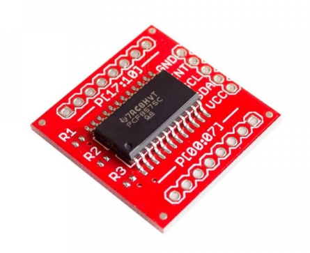
PCF8574 I/O Expander

PCF8574 I/O expander use I²C bus for communication.
More information
- documentation: https://esphome.io/components/pcf8574.html
Configuration parameters
- address: The I²C address of the driver. Defaults to 0x21.
- id: The ID to use for this PCF8574 component.
Sample configurations
pcf8574_board_basic_esp8266
Source configuration:
1 2 3 4 5 6 7 8 9 10 11 | device:
pcf8574_board_basic_esp8266:
board: nodemcuv2
mixins:
- clock_pin: GPIO5
data_pin: GPIO4
id: i2c_1
kind: i2c_bus
- address: 33
id: pcf8574_1
kind: pcf8574_board
|
The rendered configuration:
1 2 3 4 5 6 7 8 9 10 11 12 13 14 15 16 | esphome:
board: nodemcuv2
name: pcf8574_board_basic_esp8266
platform: ESP8266
i2c:
- id: i2c_1
scan: true
scl: GPIO5
sda: GPIO4
logger:
esp8266_store_log_strings_in_flash: false
level: DEBUG
pcf8574:
- address: '0x21'
id: pcf8574_1
pcf8575: false
|
PCF8575 I/O Expander
PCF8575 I/O expander use I²C bus for communication.
More information
- documentation: https://esphome.io/components/pcf8574.html
Configuration parameters
- address: The I²C address of the driver. Defaults to 0x21.
- id: The ID to use for this PCF8575 component.
Sample configurations
pcf8575_board_basic_esp8266
Source configuration:
1 2 3 4 5 6 7 8 9 10 11 | device:
pcf8575_board_basic_esp8266:
board: nodemcuv2
mixins:
- clock_pin: GPIO5
data_pin: GPIO4
id: i2c_1
kind: i2c_bus
- address: 33
id: pcf8575_1
kind: pcf8575_board
|
The rendered configuration:
1 2 3 4 5 6 7 8 9 10 11 12 13 14 15 16 | esphome:
board: nodemcuv2
name: pcf8575_board_basic_esp8266
platform: ESP8266
i2c:
- id: i2c_1
scan: true
scl: GPIO5
sda: GPIO4
logger:
esp8266_store_log_strings_in_flash: false
level: DEBUG
pcf8574:
- address: '0x21'
id: pcf8575_1
pcf8575: true
|
TLC59208F 8-bit PWM Driver
More information
- documentation: https://esphome.io/components/output/tlc59208f.html
Configuration parameters
- address: The I²C address of the driver. Defaults to 0x20.
- id: The ID to use for this TLC59208F component. Use this if you have multiple TLC59208Fs connected at the same time.
Sample configurations
tlc59208f_board_basic_esp8266
Source configuration:
1 2 3 4 5 6 7 8 9 10 11 | device:
tlc59208f_board_basic_esp8266:
board: nodemcuv2
mixins:
- clock_pin: GPIO5
data_pin: GPIO4
id: i2c_1
kind: i2c_bus
- address: 16
id: tlc59208f_1
kind: tlc59208f_board
|
The rendered configuration:
1 2 3 4 5 6 7 8 9 10 11 12 13 14 15 | esphome:
board: nodemcuv2
name: tlc59208f_board_basic_esp8266
platform: ESP8266
i2c:
- id: i2c_1
scan: true
scl: GPIO5
sda: GPIO4
logger:
esp8266_store_log_strings_in_flash: false
level: DEBUG
tlc59208f:
- address: '0x10'
id: tlc59208f_1
|